The NCP1612 is designed to drive PFC boost stages based on an innovative Current Controlled Frequency Fold-back (CCFF) method. In this mode, the circuit classically operates in Critical conduction Mode (CrM) when the inductor current exceeds a programmable value. When the current is below this preset level, the NCP1612 linearly decays the frequency down to about 20 kHz when the current is null. CCFF maximizes the efficiency at both nominal and light load. In particular, the stand-by losses are reduced to a minimum.
Like in FCCrM controllers, an internal circuitry allows near-unity power factor even when the switching frequency is reduced. Housed a SO-10 package, the circuit also incorporates the features necessary for robust and compact PFC stages, with few external components.
Near-unity Power Factor Critical Conduction Mode (CrM) Current Controlled Frequency Fold-back (CCFF): Low Frequency
On-time Modulation to Maintain a Proper Current Shaping in CCFF
Skip Mode Near the Line Zero Crossing Fast Line/Load Transient Compensation
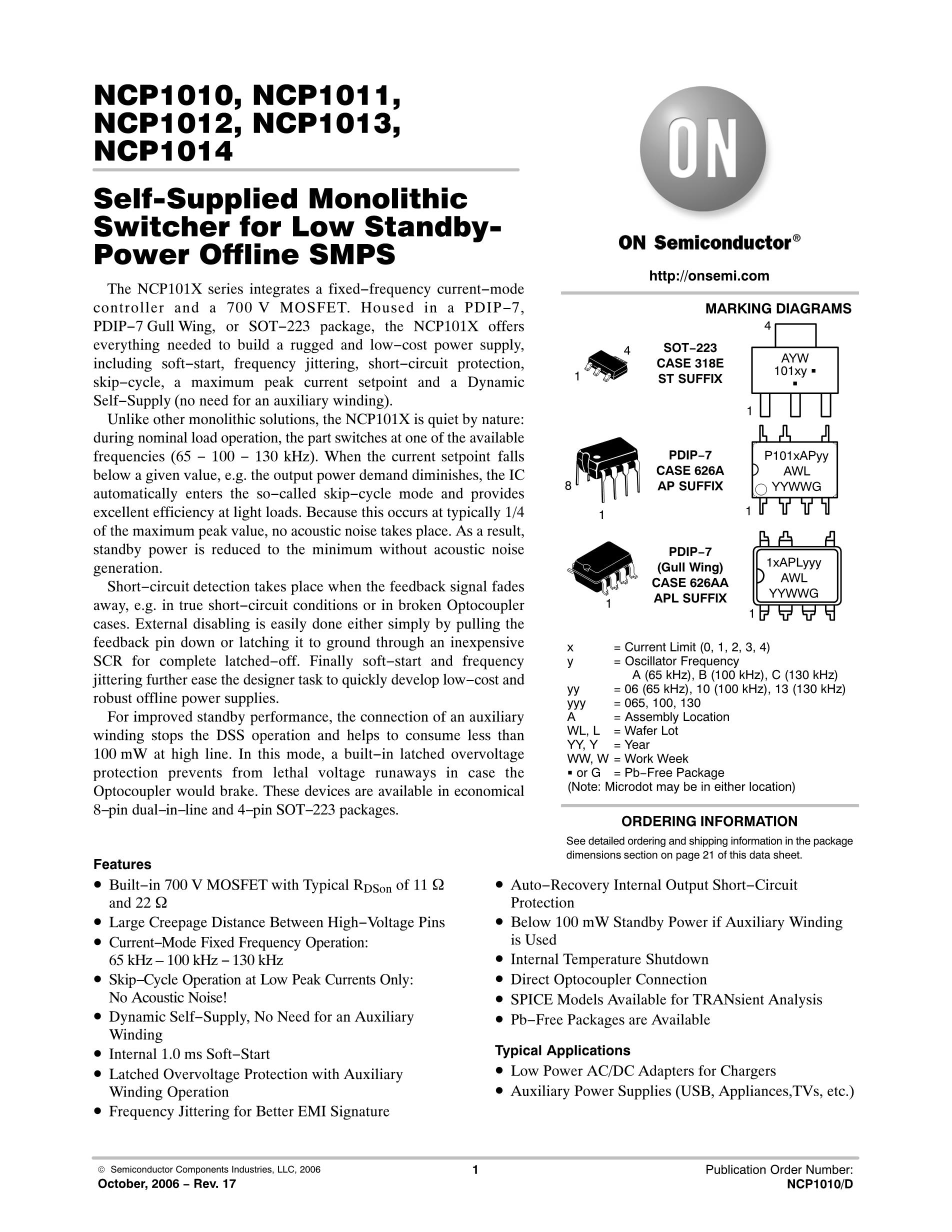
Valley Turn On High Drive Capability: -500 mA/+800 mA VCC Range: from 35 V Low Start-up Consumption Six Versions: A2, A3 and B2 (see Table 1) Line Range Detection pfcOK Signal This is a Pb-Free Device
= Assembly Location = Wafer Lot = Year = Work Week = Pb-Free Package
See detailed ordering and shipping information on page 30 of this data sheet.
Soft Over-voltage Protection Brown-out Detection Soft-start for Smooth Start-up Operation
Over Current Limitation Disable Protection if the Feedback is Not Connected Thermal Shutdown Latched Off Capability
Open Ground Pin Fault Monitoring Saturated Inductor Protection Detailed Safety Testing Analysis
Typical Applications
PC Power Supplies All Off Line Appliances Requiring Power Factor
*Please contact local sales representative for availability
Condition for Latching-off (typical threshold) VpfcOK 7.5 V VpfcOK 7.5 V VFOVP > 107%.VREF VpfcOK 7.5 V VpfcOK 7.5 V
Enabled as soon as the circuit turns on to speed-up the startup phase
The NCP1612B and NCP1612B2 large UVLO hysteresis (6 V minimum) avoids the need for large VCC capacitors and
help shorten the start-up time without the need for too dissipative start-up elements in self-powered PFC applications (where high-impedance start-up resistors are generally implemented to pre-charge the VCC capacitor).
The A1, A2 and A3 versions are preferred in applications where the circuit is fed by an external power source (from
an auxiliary power supply or from a downstream converter). Its maximum start-up level V) is set low enough so that the circuit can be powered from a 12-V voltage rail.
A2 and B2 versions are to be preferred when a signal other than a portion of the output voltage is applied to the FOVP
pin (e.g., a voltage representative of the output voltage provided by an auxiliary winding) and/or if the pfcOK pin voltage must be able to rise up to the VCC level without latching the part. Note that with the A2 and B2 versions, the fast OVP protection latches-off the circuit when triggered.
Maximum Power Dissipation = 70°C Thermal Resistance Junction-to-Air
Stresses exceeding those listed in the Maximum Ratings table may damage the device. If any of these limits are exceeded, device functionality should not be assumed, damage may occur and reliability may be affected. 1. This device contains latch-up protection and exceeds 100 mA per JEDEC Standard JESD78. 2. "VCONTROLMAX" is the pin3 clamp voltage and "VDRV" is the DRV clamp voltage (VDRVhigh). If VCC is below VDRVhigh, "VDRV" is VCC. 3. Recommended maximum Vsense voltage for optimal operation V. 4. The recommended maximum voltage not to exceed remains -0.3 V but Figure 2 short negative spike on the CS/ZCD pin is typically
acceptable. However, it implies the full characterization of the circuit embedding the NCP1612, including at maximum temperature conditions, during which no erratic operation is observed. If otherwise noted, we recommend to clamp the negative voltage on the CS/ZCD pin to avoid carrier injection within the die. 5. Maximum CS/ZCD current that can be injected into pin6 (see Figure 3). 6. This device(s) contains ESD protection and exceeds the following tests:
Human Body Model 2000 V per JEDEC Standard JESD22-A114E Machine Model Method 200 V per JEDEC Standard JESD22-A115-A Charged Device Model Method 1000 V per JEDEC Standard JESD22-C101E


 Required
, Critical Conduction (CRM) 10-SOIC")